VIZid Mesh
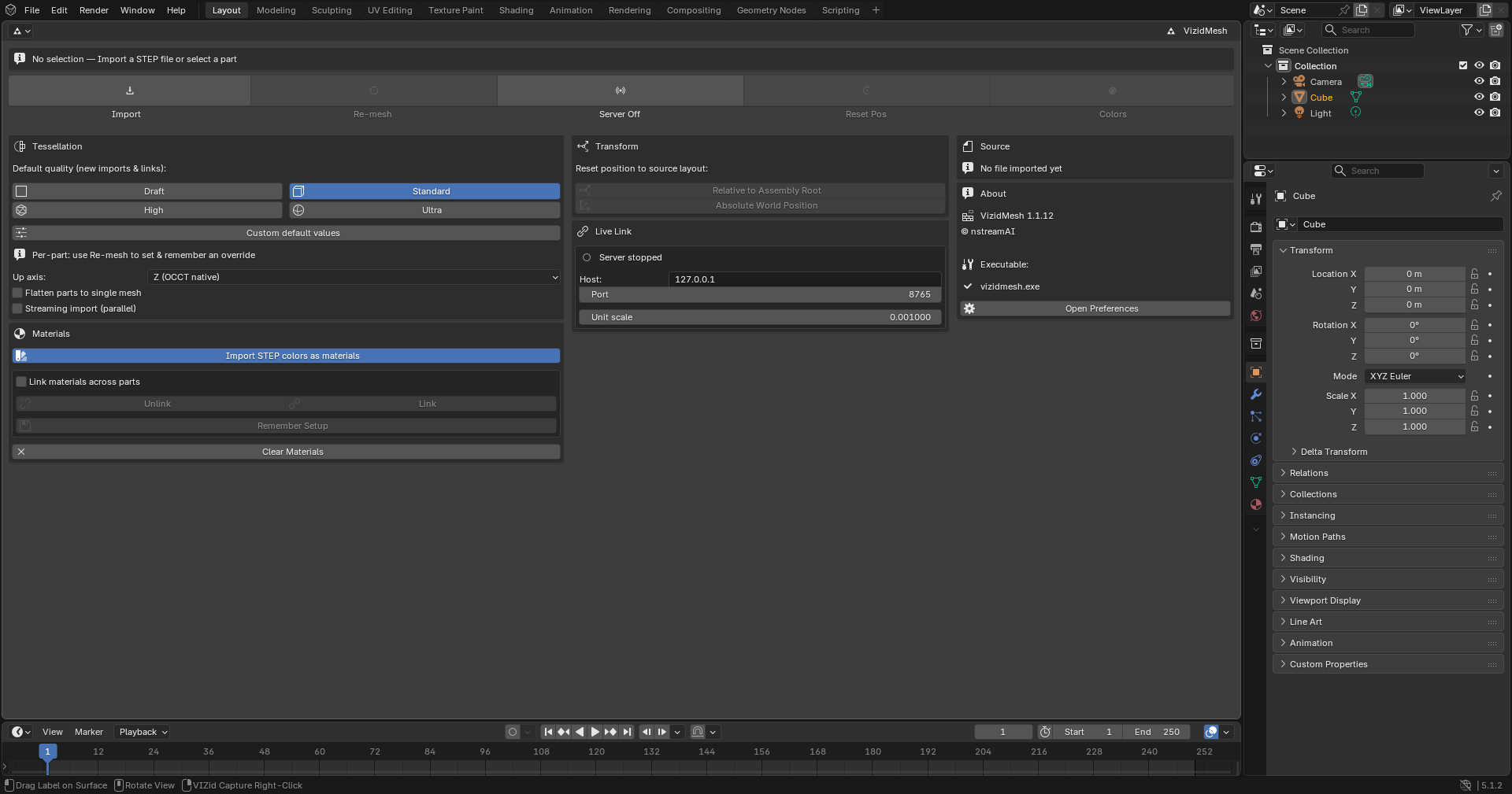
The VIZid Mesh panel.
VIZid Mesh imports CAD geometry from STEP (.stp / .step) files and
tessellates it into clean, render-ready meshes. The tessellation is produced by
a bundled native converter aimed at studio-grade surface quality, with
iso-curve aligned grids rather than generic triangulation.
Beyond a one-off import, VIZid Mesh keeps a part connected to its CAD source: an imported assembly can be re-tessellated at a different quality at any time while preserving the transforms and materials applied to it in the scene, and a TCP VIZid Bridge streams parts straight from a running PTC Creo or Dassault SOLIDWORKS session so they appear and re-mesh in VIZid Suite as the CAD model changes.
The same controls drive both sources. Whether geometry came from an imported STEP file or a live CAD sync is simply a property of the active selection, so the quality, transform and material actions all target whichever assembly is active.
Reference
- Editor:
Mesh
- Panel:
(3D Viewport)
VIZid Mesh has two homes. In VIZid Suite it fills the dedicated Mesh editor, which lays out the controls as an adaptive dashboard that reflows between one, two and three columns to fit the editor’s width. When the add-on is installed in stock Blender, the same controls appear in the VIZid Mesh tab of the 3D Viewport Sidebar, one panel per section.
Importing a STEP File
Reference
- Editor:
Mesh
- Panel:
- Menu:
To import CAD geometry, use Import STEP File and pick one or more .stp /
.step files. Each file is converted and added to the scene as a collection
named after the file, with the assembly hierarchy preserved as nested
collections and empties and one root empty that acts as a single transformable
handle for the whole assembly.
A STEP file can also be dragged from the file browser into the 3D Viewport, or imported from the standard menu.
The current source file is shown beneath the import button, with a button to open its containing folder.
The settings used for the conversion are read from the panel at import time:
- Up axis
The axis treated as up in the output, offered as Z (OCCT native) (the default), which keeps the STEP file’s native orientation, and Y (Maya / Unreal), which bakes a \(+Z\\rightarrow+Y\) rotation into the output for applications that expect a Y-up convention.
- Flatten parts to single mesh
Collapses the per-part scene hierarchy into one FBX mesh, rather than keeping each part and body as a separate object. Off by default.
- Import STEP colors as materials
When enabled, surface colours stored in the STEP file are read and emitted as one material per unique colour.
- Link materials across parts
When off (the default), each part or body receives its own copy of every material, so one part’s shading can be edited without affecting the others. When on, parts that share a colour share a single material. This is best set before importing; the Link and Unlink buttons change it for geometry that is already in the scene.
- Streaming import (parallel)
Extracts every part once and then meshes the parts in parallel, importing each as it finishes, so geometry appears progressively. Subsequent imports of the same file are served from a cache.
A progress indicator in the status bar reports the part currently being meshed. The import runs in the background and can be cancelled with Esc.
Tessellation Quality
The quality presets.
The density and accuracy of the mesh is controlled by a quality preset. Four presets are available:
- Draft
Coarse tessellation. Fastest, but blocky on curved surfaces.
- Standard
Balanced quality and speed. This is the recommended default.
- High
Fine tessellation, roughly three times the triangle count of Standard.
- Ultra
studio-grade tessellation, roughly ten times the triangle count of Standard.
Selecting a preset sets the default quality used for new imports and new live syncs; it does not re-mesh existing geometry on its own. Per-part overrides are set when re-meshing (see Re-meshing).
Custom Values
Enabling Custom values replaces the preset with explicit tessellation parameters:
- Chord tolerance
The maximum distance between the mesh and the underlying surface. Lower values produce a finer mesh. The Standard preset uses
0.6 mm.- Angle tolerance
The maximum angular deviation allowed between adjacent mesh chords. The Standard preset uses
20°.- Crease angle
The dihedral angle above which an edge is treated as a hard crease,
30°by default.- Prefer quads
Emits a quad-dominant mesh where possible.
- Defeature small features
Drops tiny sliver faces and extreme-aspect features before meshing. This is on by default.
- Weld coincident vertices
Enables an exact-coincidence weld after meshing. Rarely needed.
Re-meshing
An imported or live-synced assembly can be re-tessellated at any time without losing the work done on it in the scene. Re-meshing matches the new geometry to the existing objects, swaps only the mesh data, and keeps each object’s transform, parenting, modifiers and materials. Parts that the CAD source has gained appear as new objects; parts it has lost are hidden and tagged as orphaned rather than deleted, and can be revealed and kept from the panel.
The scope of a re-mesh follows the selection:
With a single part selected, only that part is re-meshed.
With a sub-assembly empty or its collection active, that sub-assembly is re-meshed.
With the assembly root active, the whole assembly is re-meshed.
In the Mesh editor, the dashboard’s single primary Re-mesh button opens a quality picker for the active part or assembly. The picker lists Draft, Standard, High and Ultra, followed by Custom…. Clicking one of the four presets re-meshes immediately; Custom… instead opens a dialog for explicit values. The quality chosen here becomes that entity’s override: it is remembered and reapplied on every later update, so a part keeps its quality across edits and live updates regardless of the global default.
The sidebar exposes the same actions as separate buttons: Re-tessellate Selection for the active part or sub-assembly, and Re-tessellate Whole Assembly for everything in the last-imported assembly.
Transform and Materials
Reference
- Editor:
Mesh
- Panel:
The reset buttons snap an assembly back to the layout its source specified – the STEP layout for an imported assembly, or the CAD layout for a live-synced one:
- Relative to Assembly Root
Restores each part’s position relative to the assembly-root empty, keeping wherever the whole assembly was moved to.
- Absolute World Position
Restores the whole assembly, including the root empty, to its original world position.
The material actions manage the materials created from STEP colours:
- Link / Unlink
Switch the whole scene between shared materials (parts of the same colour share one material) and independent per-part copies.
- Remember Material Setup
Records the current materials as the setup that re-meshing must preserve, storing each part’s mapping from material slot to STEP colour. Run this once on scenes imported before this feature existed, or any time after re-arranging materials, so that pasted, renamed or custom materials survive a re-mesh.
- Re-apply STEP Colors
Re-meshes the active assembly and forces the STEP file’s surface colours back on, discarding manual material edits on the affected parts.
- Clear Materials on Selected
Removes every material slot from the selected objects.
VIZid Bridge

The VIZid Bridge panel.
Reference
- Editor:
Mesh
- Panel:
The VIZid Bridge connects VIZid Suite directly to a running CAD session, so that parts pushed from PTC Creo or Dassault SOLIDWORKS are tessellated and placed in the scene as the CAD model changes. The CAD-side plug-ins are documented in CAD VIZid Bridge.
For an optional standalone relay that keeps the CAD connection alive across VIZid Suite restarts, see VIZid Bridge Service (advanced).
VIZid Suite hosts the server; the CAD plug-in connects to it as a client over TCP. Before starting, set the endpoint:
- Host
The address the server binds to.
127.0.0.1restricts it to the local machine.- Port
The TCP port the server listens on. This must match the port configured in the CAD plug-in; the default is
8765.- Unit scale
A uniform scale applied to the whole linked assembly. STEP geometry is in millimetres, so the default of
0.001converts to metres so that dimensions read correctly in a metric scene. Use1.0to keep millimetres or0.0254for inch scenes. This applies to new imports; changing it once parts already exist takes effect only after a Reset to … (absolute), which re-applies the scale at the assembly-root empty.
Start Server begins listening; the button becomes Stop Server while the server is running. The panel reports the connection state in words – Listening on host:port once the server is up, Creo connected when a CAD client attaches, Listening — Creo disconnected after it drops, and Server stopped once stopped. The server labels every client Creo internally, so a connected SOLIDWORKS session is reported the same way. The running state is saved with the .blend file and the server restarts automatically when the file is reopened.
Receiving Parts
When the CAD plug-in connects it sends the scene, and thereafter streams updates as the model changes. Each part arrives as its own geometry, is tessellated by the converter at the part’s resolved quality (its override, or the global default), and is placed into a VIZid Mesh Live collection following the CAD assembly hierarchy. Multi-body parts are kept as separate body meshes grouped under the part.
Live updates keep the transforms and materials applied to a part in the scene by default. A move made in the CAD tool is detected and propagated to the corresponding part or sub-assembly, while geometry that has not changed is left where it was placed in the scene. A drag that changes only a part’s position is applied directly, without re-tessellating its geometry.
Each part’s STEP data is held in an encrypted cache, so a live-synced part can be re-meshed at a different quality, or moved back to its CAD layout, even when no CAD session is connected. The cache size is shown in the panel, with a button to clear it.
Quality, transforms and materials for live-synced parts use the same controls as imported parts, described in the sections above.
Troubleshooting
When a live update fails it is made visible rather than swallowed: the failure
is appended to %TEMP%\\vizidmesh_livelink_errors.log – which survives a
later crash, unlike the console – and the panel status switches to a FAILED
line naming what went wrong. A 15-minute watchdog backs this up: a part whose
converter hangs or is killed without returning a result is failed after that
timeout so the pipeline never freezes waiting on it.
A few common messages and what they mean:
FAILED: … — see System Console / vizidmesh_livelink_errors.log – an update could not be applied; the log holds the full traceback.
No cached STEP for … – a re-mesh was requested with no CAD session connected and the encrypted cache cleared, so there is nothing to re-mesh offline. Reconnect the CAD sync to refill the cache.
vizidmesh.exe not found — set it in Preferences – the native converter could not be located; set its path as described in Preferences.
Preferences
Reference
- Editor:
Preferences
- Panel:
The add-on’s own settings live in :
- VIZid Mesh executable
The path to the native converter,
vizidmesh.exe. Locate opens a file selector to point at it by hand, and Auto-detect searches the usual install locations and remembers the first hit. Left blank, the add-on auto-detects on each run. If the converter cannot be found, operators report vizidmesh.exe not found. Set it in Preferences → Add-ons → VIZid Mesh – this panel is where to fix it.- Default quality
The preset (Draft, Standard, High or Ultra) used for new imports and live syncs before it is changed in the panel.
- Keep temp FBX files
Leaves the intermediate FBX next to the source instead of deleting it, which is useful when debugging colour assignment or topology.